16th January 2010
This was my attempt at a fairly compact loop for the LF bands, originally built for when Walter DI2AG had an experimental transmitter on 440KHz. I had a small 18 inch square conventional frame at the time but decided to wind the larger one as a spiral to make it easier to move around the house and easier to store when not in use.
Had I realised when I started this loop how much work was involved in drilling all the holes in the PVC tube and then feeding the wire through those holes I would probably have used wooden spars drilled and pegged which would have made winding the loop easier if a little heavier and not as acceptable to my XYL when I have it sitting on the dining room floor.
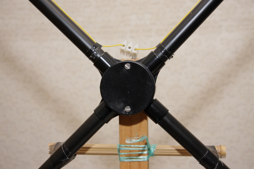
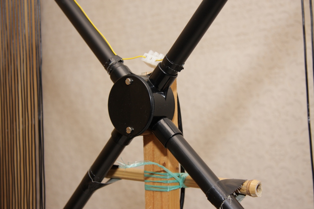
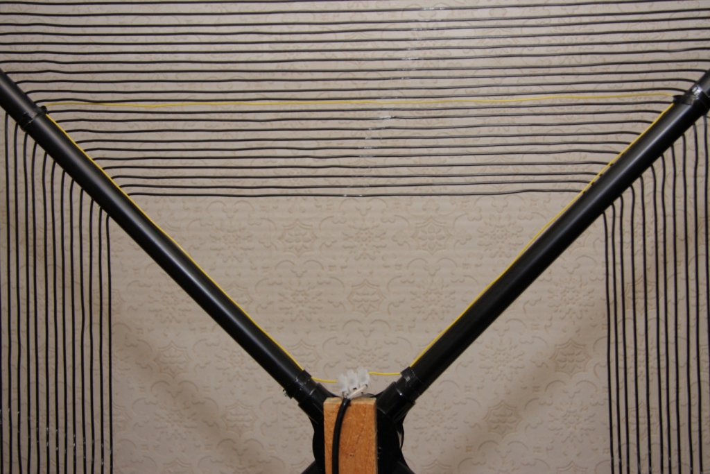
I used 20mm PVC conduit pipe for the diagonal arms joined in the center by using a round conduit junction box. I could only get a three way fixing box so drilled the box and put in a female adaptor for the fourth diagonal. A four way box is available and this would be the best way to go as the female adaptor tends to be a little loose.
There is some debate as to whether black PVC is unsuitable for antenna work as it is supposed to have some carbon in it to make it black so perhaps white conduit would be better.
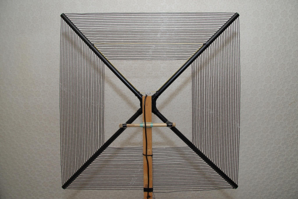
The loop is 75cm square and 107cm diagonally corner to corner.
It has 29 turns with the holes spaced 10mm apart and I drilled the first hole 5mm from the outer end of the tube, when drilling the holes don't make them too tight a fit for the wire you use as feeding the wire through the pipe can be difficult. I think that I used about 64.5m of 24/0.2mm stranded equipment wire to wind the loop. Another point to note is not to put too much tension on the windings as the PVC tubing tends to bow.
The pick up loop at the moment is a triangular shape fed from the center running up the upper diagonals and across between turns 19 and 20, in the photo it can be seen as a yellow wire. I've been doing some trials with different shapes and sizes using a 500KHz generator a few feet away as a signal source which wasn't very satisfactory but then realised a few days ago that NT the NDB for Newcastle airport about six miles away is on 352KHz which will give me a better signal source to play about with.
____________
19th January 2010: Over the weekend I did some further trials with shapes and sizes of pick up loop and reached a point where a square loop set against turns 19 gave the best received level so far and stopped at that point to air test for a few days. The changes in received level recorded while gradually reducing the loop size were relatively small just 1.5dB from a point close to the outer edge to it's new position at turn 19. For the triangular loop previously described I had used thin wire, 7/0.2mm, recovered from a length of multi-core cable and for the new loop I used a much heavier speaker wire. One thing that was noted with the different wire and will have to be checked again by a further test using the thinner wire is that the tuning peak of the loop is now not as sharp as it was previously.
____________
21st January 2010: After further trials today I have finished up with a square pick up loop located 8 turns from the inner of the loop, this to date gives the best received level. I have also gone back to the 7/0.2mm wire for the pick up as it gives the same receive level as the thicker speaker wire and also appears to give a sharper peak in tuning.
____________
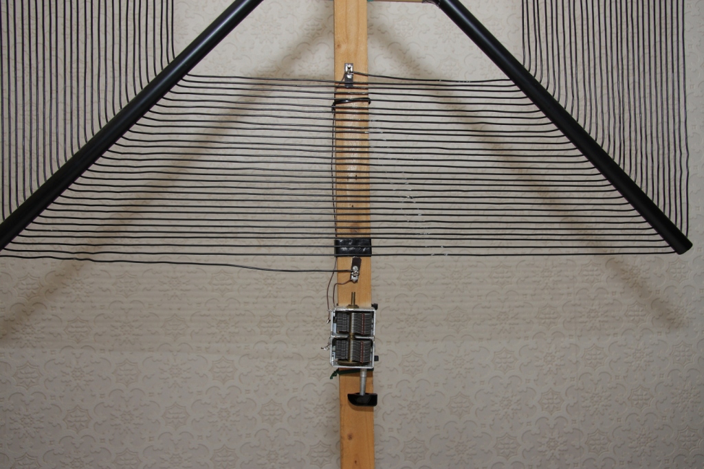
21st March 2010: I was looking through G3ZJO Eddie's blog and noted his use of a ferrite ring as a pick up instead of a wire loop. It would be difficult to place a toroid on any of the turns of my loop so I first of all tried a ferrite rod, something I'd done before without much success and this time was no better. I then looked around the shack to see what else I could try and found a clip-on suppressor, slightly smaller (32mm x 19mm with 7mm hole diameter) but similar in appearence to Maplin's N95AB.I used hook up wire and wound four turns onto one half of the clip-on then clipped it around the outer turn of the loop, the result was something of a surprise as my reference signal on 352KHz was the same strength as it was with the original pickup loop. Various positions for the clip-on pickup were tried and there were only small variations in the received signal. As clipping it on to the outer turn of the loop at the bottom keeps the coax away from the spiral coil it was left in that position. Different numbers of turns were tried on the pick up but there were no differences between one to four turns so I settled for two turns of 1.5mm wire as this filled up the space along with the loop wire and made the clip-on a tight fit and less liable to move.
Now for the acid test, I retuned the receiver to 502.4KHz, put the loop on the lawn about 9m from the house and watched for a signal. Nothing! Out to the loop to check and found that I'd knocked the capacitor so with my trusty ICF-SW100 portable I tuned the loop for maximum noise. What a difference, PA0A at -6dB and G4JNT at -23dB on WSPR and this was around 13:00 UTC, G4JNT is normally no better than -27dB if seen at all here in the middle of the day. Turning the loop to favour Holland had PA0A's next signal recorded at 0dB.
All in all a very useful and productive modification and something to explore further, hopefully there are no side effects like increased sensitivity to electronic noise such as a neighbours PC switch mode supply.
____________
The tuning capacitor is a 500pf x 500pf double gang with a reduction drive and is wired in series to give 250pf, this can tune the loop down to 340KHz and up to 1250KHz (for a bit of broadcast dxing).
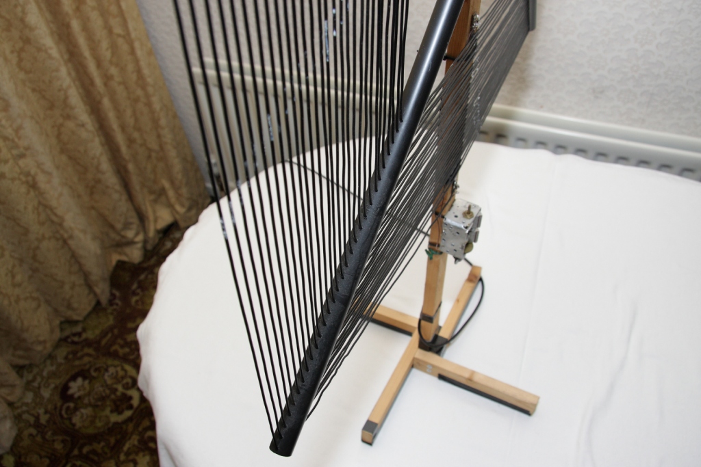
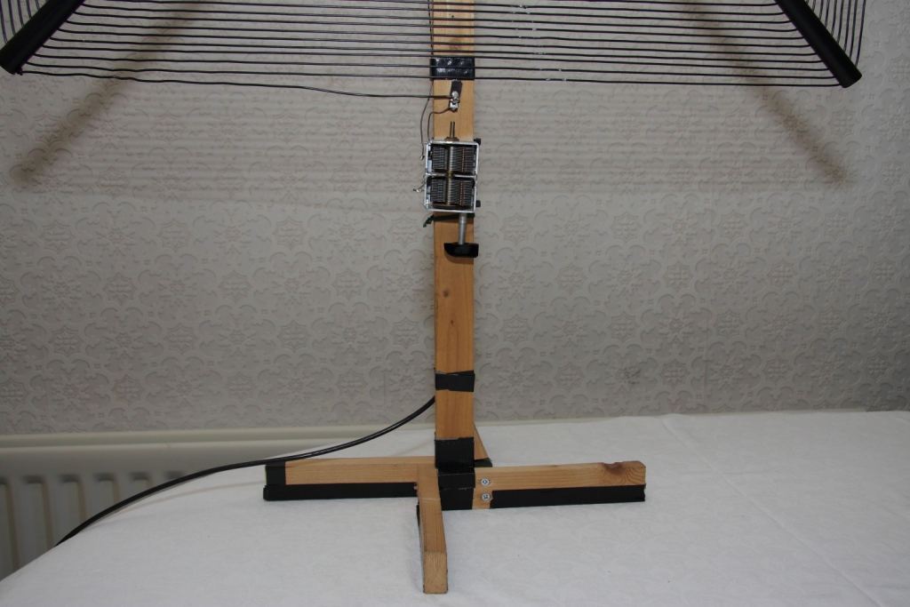
The wooden support is made from probably what they call 4cm x 2cm dressed which makes the dimensions a bit smaller than that, not being a chippie measurements of dressed and undressed timber always confuses me. I made a simple base using the same wood which seems to do the job nicely, the loop support can be lifted out of the base so that it can be placed flat against a wall for storage when not in use.
I'm still a bit confused as to the expected operation of a spiral loop but mine receives it's maximum signal off the edge of the spiral and it's null off the face.